
")

Air Bearing Turbo Blower
The Air Bearing Turbo Blower is a type of blower where, under the high-speed rotation of the blower rotor, a dynamic pressure effect is generated between the rotor and the surface of the foil bearings, creating a high-pressure air film that lifts and suspends the rotor.
Selection and Parameters
| Total Power (kW) | 15 | 20 | 30 | 40 | 50 | 60 | 75 | 90 | 110 | 130 | 150 | 175 | 200 | 250 | 300 | |
| Shaft Power (kW) | 12 | 17 | 26 | 35 | 44 | 53 | 68 | 82 | 100 | 118 | 136 | 159 | 183 | 225 | 273 | |
| Model/Parameter | KFA20 | KFA30 | KFA40 | KFA50 | KFA70 | KFA80 | KFA100 | KFA125 | KFA150 | KFA75 | KFA200 | KFA235 | KFA270 | KFA335 | KFA400 | |
| Flow Rate (m³/min) | ||||||||||||||||
| Pressure (kPa) | 40 | 14 | 21 | 33 | 45 | 55 | 66 | 80 | 96 | 119 | 141 | 162 | 198 | 215 | 270 | 324 |
| 50 | 11 | 16 | 26 | 36 | 45 | 54 | 69 | 83 | 108 | 129 | 140 | 172 | 192 | 245 | 302 | |
| 60 | 9 | 13 | 22 | 31 | 40 | 49 | 64 | 77 | 92 | 109 | 126 | 147 | 167 | 210 | 255 | |
| 70 | 11 | 19 | 28 | 36 | 43 | 55 | 67 | 81 | 95 | 112 | 130 | 149 | 189 | 226 | ||
| 80 | 17 | 25 | 31 | 38 | 50 | 61 | 72 | 87 | 104 | 120 | 130 | 168 | 205 | |||
| 90 | 16 | 23 | 28 | 34 | 44 | 54 | 64 | 80 | 94 | 107 | 120 | 151 | 186 | |||
| 100 | 25 | 31 | 40 | 50極 | 59 | 74 | 86 | 100 | 112 | 141 | 179 | |||||
| 110 | 29 | 37 | 45 | 55 | 68 | 79 | 91 | 101 | 134 | 161 | ||||||
| 120 | 34 | 42 | 51 | 63 | 74 | 83 | 94 | 125 | 149 | |||||||
| Structure Type | Single Impeller | Dual Impeller | ||||||||||||||
| Dimensions (mm) | 1420L*700W*1500H | 1535L*900W*1680H | 1705L*1040W*1980H | 2100L*1500W*2000H | ||||||||||||
| Cooling Port Diameter | DN65 | DN100 | DN125 | DN150 | ||||||||||||
| Outlet Pipe Diameter | DN100 | DN150 | DN200 | DN250 | DN300 | DN350 | DN400 | |||||||||
| Weight (kg) | 220 | 330 | 350 | 380 | 650 | 690 | 750 | 800 | 850 | 950 | 1000 | 1300 | 1400 | 1700 | 1780 | |
Note: KFA100 (KF - Kaifeng, A - Air Suspension, 100 - Horsepower)
Performance Comparison: Air Bearing Turbo Blower vs. Traditional Blower
| Fan Type | Roots Blower | Single-Stage High-Speed Centrifugal Blower | Multi-Stage Centrifugal Blower | Air Bearing Turbo Blower |
| Bearing Type | Ball Bearing | Ball Bearing | Ball Bearing | Air Bearing |
| Bearing Lubrication | Required | Required | Required | Not Required |
| Bearing Life | 1-2 Years | 3-5 Years | 2-3 Years | 200,000 Start-Stop Cycles |
| Bearing Loss | 2-5% | 2.5% | 2-5% | 1% |
| Motor Type | Low-Speed Asynchronous Motor | Asynchronous AC Motor | Low-Speed Asynchronous Motor | High-Speed Permanent Magnet Synchronous Motor |
| Motor Efficiency | 85-90% | 85-90% | 85-90% | Above 95% |
| Motor Transmission Type | Belt or Coupling | Coupling | Coupling | Direct Drive |
| Motor Speed Control | Not Adjustable | Adjustable | Not Adjustable | Precise Control |
| Impeller Type | Cast Two or Three-Lobe Impeller | Aluminum Alloy Ternary Flow Impeller | Welded/Cast Carbon Steel or Aluminum Impeller | Aluminum Alloy Ternary Flow Impeller |
| Impeller Life | 5-8 Years | 15 Years | 10 Years | 20 Years |
| Impeller Efficiency | Low | Relatively High | Relatively High | High |
| Control Method | Outlet Throttle Frequency Conversion | Inlet Throttle Frequency Conversion | Inlet Throttle Frequency Conversion | Frequency Conversion |
| Wear Parts | Bearings, Gears | Bearings, Gears, Lubrication Pump | Bearings, Seals | Filter Cotton |
| Lubrication | Periodic Addition | Periodic Addition | Periodic Addition | No Lubrication Required |
| Cost | Medium | High (Imported) | Medium | Low |
| Overall Efficiency | Around 65% | Around 65% | Around 65% | Above 80% |
| Procurement Cost | Low | High (Imported) | Relatively High | Relatively High |
Air Suspension Motor Assembly
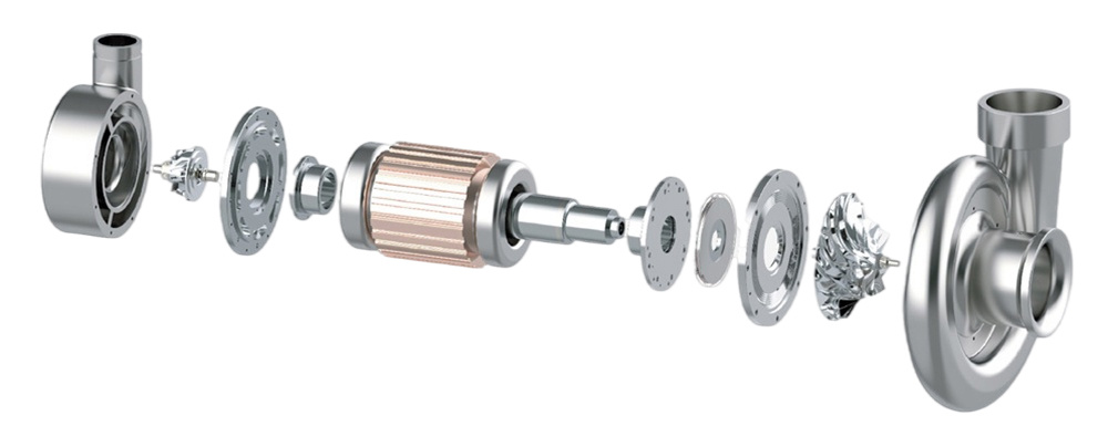
The ternary flow centrifugal impeller technology originates from aerospace engine technology. It abandons the traditional guide vane adjustment method and adopts a frequency conversion drive adjustment method, allowing for adjustable speed ranges and expanding the operational range of the blower.
Air suspension bearings are commonly used in the aerospace field and are often considered core components of certain systems. Without the use of any lubricants, they offer zero maintenance, zero pollution, long-term stable operation, and can function normally within a wide temperature range of -180°C to 600°C.
Permanent magnet synchronous ultra-high-speed motors are a new type of motor that has emerged with advancements in permanent magnet material technology, semiconductor technology, and control technology. They can achieve speeds of up to 400,000 revolutions per minute or more, with motor efficiency exceeding 95%. These motors are characterized by high speed, low vibration, low noise, compact size, simple structure, and minimal electromagnetic radiation, making them one of the most energy-efficient and high-performance motors currently available.
Focusing on high frequency, with a carrier wave of up to 16kHz and an output frequency of up to 800Hz, they can easily drive high-speed motors. Excellent loss suppression and thermal management ensure high-frequency output without derating, making them suitable for various harsh operating environments. High-performance sensorless vector control technology offers good parameter adaptability, high control performance, low output harmonics, and reduced motor heating. Intelligent self-learning allows for one-click identification of motor and control parameters, significantly reducing debugging difficulty and workload.
Previous
Previous
Air Suspension Vacuum Pump


Address: Building C, Pengyao Environmental Protection Technology Innovation Park, No. 25 Saite Avenue, Yixing City, Jiangsu Province
Contact: Mr.Chen
E-mail: j.chen@kaifengtech.com

WeChat official account
Copyright © 2025 Yixing Kaifeng Technology Co., Ltd | SEO
Power by: www.300.cn


